1 MHz–4 GHz · Battery powered · Calibrated power

Precision RF power.
Near-field insight you can feel.

A portable RF wattmeter with calibrated power measurement, Windows GUI and fast USB logging. A handheld near-field analyzer that guides your probe with live sound and vibration. Both in one PNFA.

From €1,090 excl. VAT · PNFA Monitor software included

One instrument. Two workflows.

Meet PNFA

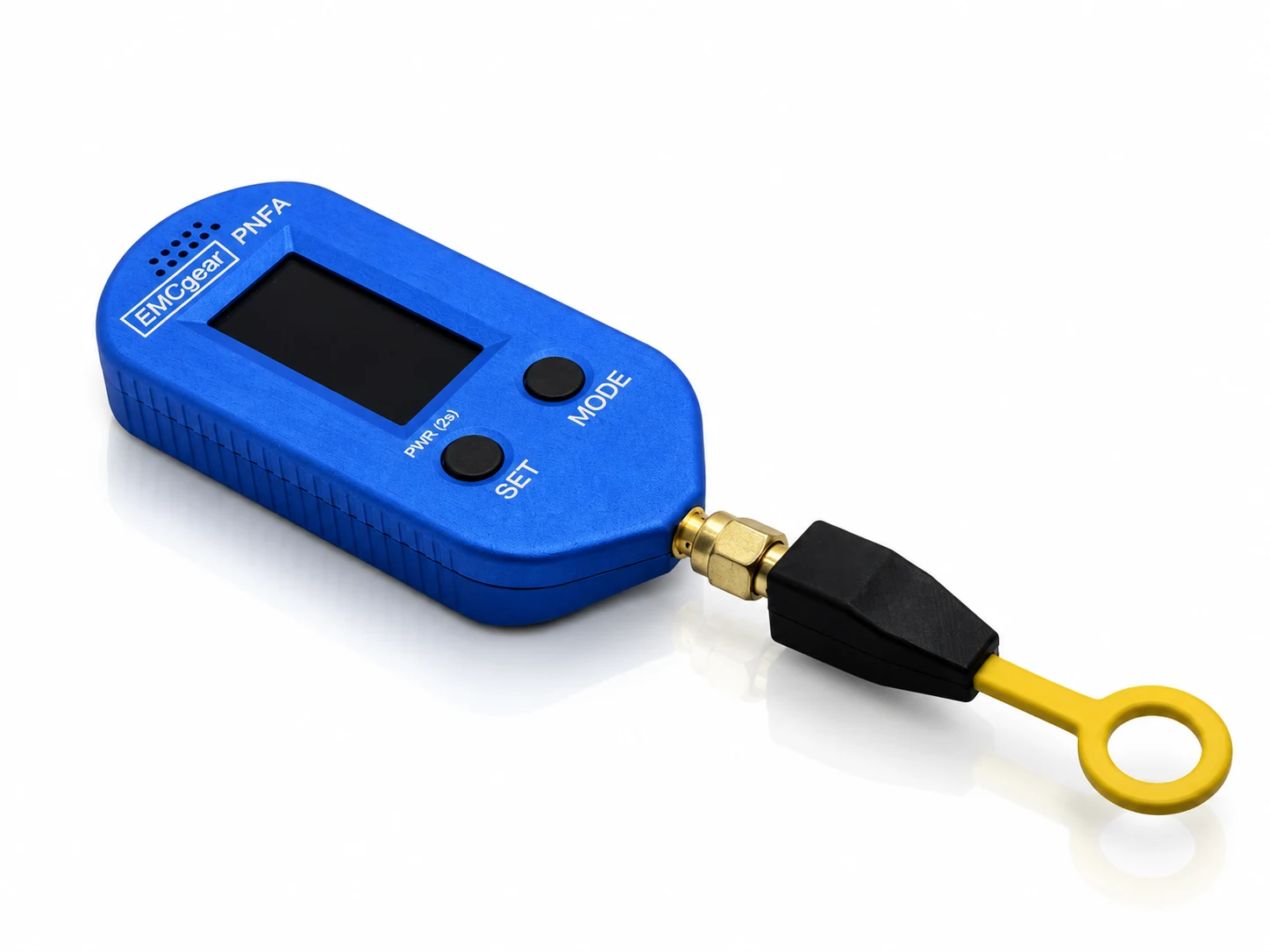
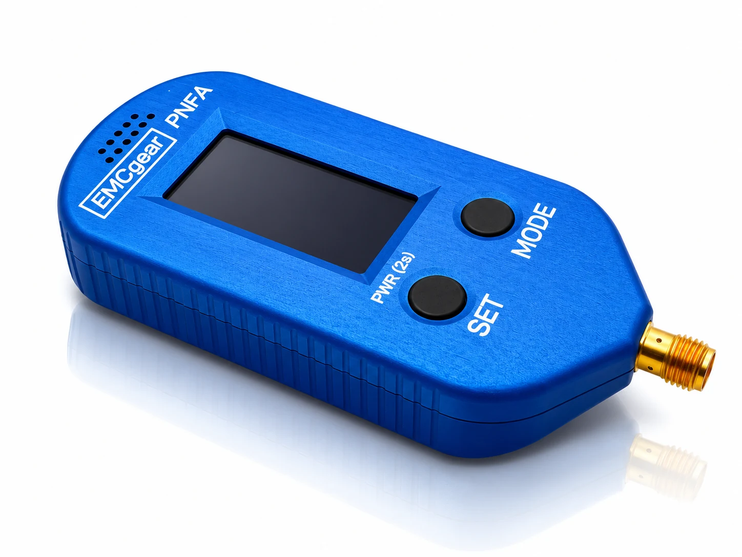
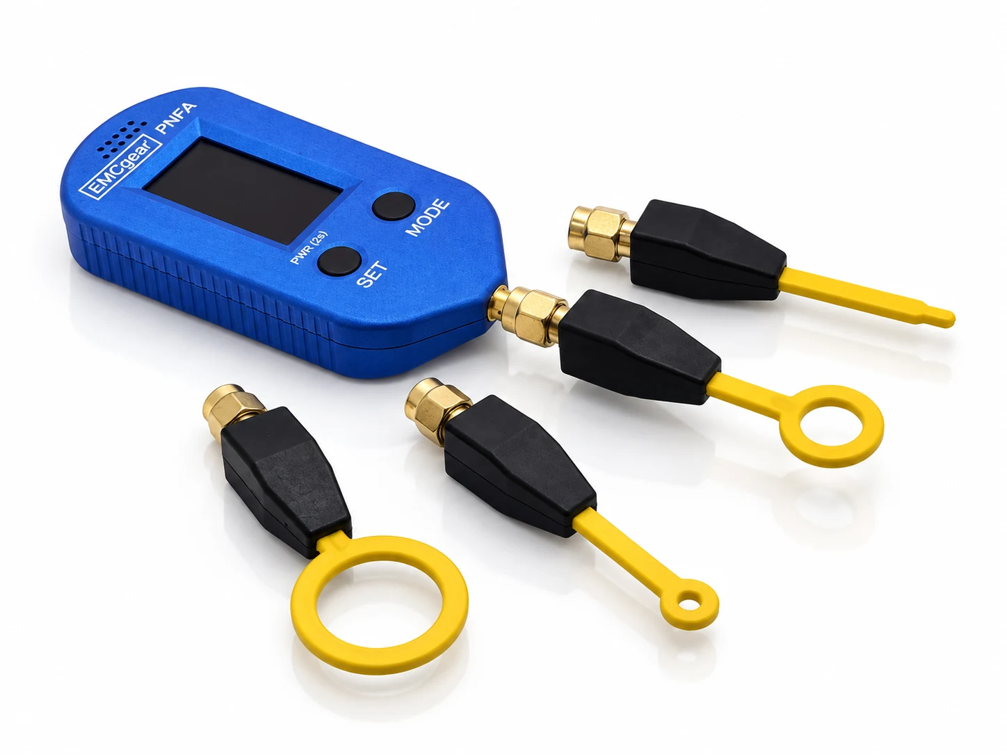
Blue anodized PNFA handheld RF instrument with OLED display, two controls and SMA connector
Calibrated RF powerAcoustic + haptic feedback
Typ. ±0.2 dBRF power accuracy · 1 MHz–3 GHz¹
Up to 1 kSa/s*USB RF-level streaming & logging
4 hardware filtersSelectable RF input filter bank
Hear it. Feel it.Live acoustic & haptic guidance

¹ Fixed high precision mode for a known frequency; typ. ±0.4 dB at 3–4 GHz. See accuracy and range details. * In combination with PNFA Monitor for Windows. Maximum RF-level stream rate; effective rate depends on mode and setup. See recording details.

Start with what you need to measure

One PNFA. Two clear ways to work.

Choose the connection for the job. The instrument, display and PC software work together across both workflows.

01 · RF wattmeter

Measure RF power. Capture the changes.

Connect a known RF source through the 50 Ω SMA input, with external attenuation where needed. Read calibrated power in dBm or watts, then record how the level changes over time.

  • Frequency-corrected, high precision measurement
  • Battery operation at the bench or in the field
  • Windows GUI, time graphs and fast CSV logging
Explore RF power measurement
Portable RF wattmeter

Small enough to carry.
Precise enough to quantify.

Check RF sources, compare output levels and record drift or intermittent activity. Enter the known signal frequency in Fixed high precision mode: PNFA selects the input filter and applies frequency-dependent calibration correction.

  • 1–4000 MHz frequency entry in whole-MHz steps
  • −50 to +20 dBm calibrated measurement range
  • Auto, Direct or internal attenuator input-path selection
  • dBm and watts, plus calculated 50 Ω Vrms / Irms

Fixed mode corrects the response at the entered frequency. Other signals within the selected broad filter band can still contribute to the reading.

See RF power kit · €1,149
Absolute RF power accuracy
±0.2 dB typ.

1 MHz–3 GHz · ±0.5 dB max.

±0.4 dB typ.3 GHz–4 GHz · ±1.0 dB max.
Calibrated range
70 dB −50 to +20 dBm
Full measurement range
Approx. 95 dB Approx. −75 to +20 dBm

Figures are the datasheet’s absolute RF power accuracy specification. Use a known signal frequency, the correct input path and the calibrated range. Probe coupling, cables and external attenuators contribute separately to the uncertainty of the complete setup.

Read the datasheet · PDF
PNFA fitted directly with an NFPP H-field loop probe for handheld near-field work
The PNFA difference · Feedback in your hand

Hear the change.
Feel the hotspot.

Move the probe. Hear and feel the RF level change. PNFA’s combined acoustic and haptic feedback makes source localization a direct, hands-on process — with your attention on the probe position.

Start with Full band to find the strongest broad band, then select that filter to follow level changes. You can begin troubleshooting without configuring a frequency sweep, span or resolution bandwidth.

  • Tone or Geiger-style audio to follow changing levels
  • Haptic vibration for a tactile indication
  • Audio and haptics together, independently, or off
  • Low, Medium and High feedback sensitivity

Feedback follows the live corrected level even when the display uses Average, Peak or Max Hold. Feedback sensitivity changes the indication, not RF gain or measured power.

Direct level response

Follow a selected band without waiting for a frequency sweep.

PNFA detects RF level through a broad input filter rather than sweeping frequency points. With one band selected, there is no frequency sweep to wait for as you move the probe. Full band sequentially compares four filter paths; it reports the strongest band, not their summed power. Use a spectrum analyzer when you need individual frequencies resolved.

  1. 1
    Connect a probe

    Choose an H-field loop or E-field probe for the area of interest.

  2. 2
    Enable feedback

    Start with Medium sensitivity and audio, haptics or both.

  3. 3
    Locate and compare

    Follow the level change. Keep probe spacing and orientation consistent.

Four selectable hardware RF filters

Focus your search. Reject out-of-band energy.

A bank of four physical RF input filters helps separate broad frequency regions. Select one for a focused comparison, or let Full band identify the strongest response.

LP · Low-pass

<30 MHz

CISPR band B

Low-frequency RF within PNFA’s 1 MHz lower operating limit.

BP1 · Band-pass

30–300 MHz

CISPR band C

Compare activity in the lower VHF region and above.

BP2 · Band-pass

300–1000 MHz

CISPR band D

Focus on the middle RF band without lower-band energy dominating.

HP · High-pass

1–4 GHz

CISPR band E

Explore the upper part of PNFA’s operating range.

Ranges are nominal, within the 1 MHz–4 GHz operating range; filter edges are not ideal cutoffs. CISPR labels indicate nominal band alignment within PNFA’s operating range. These are broad RF filters, not narrowband channels or a frequency spectrum.

PNFA Monitor included · Windows 10 / 11

From a live reading to a useful record.

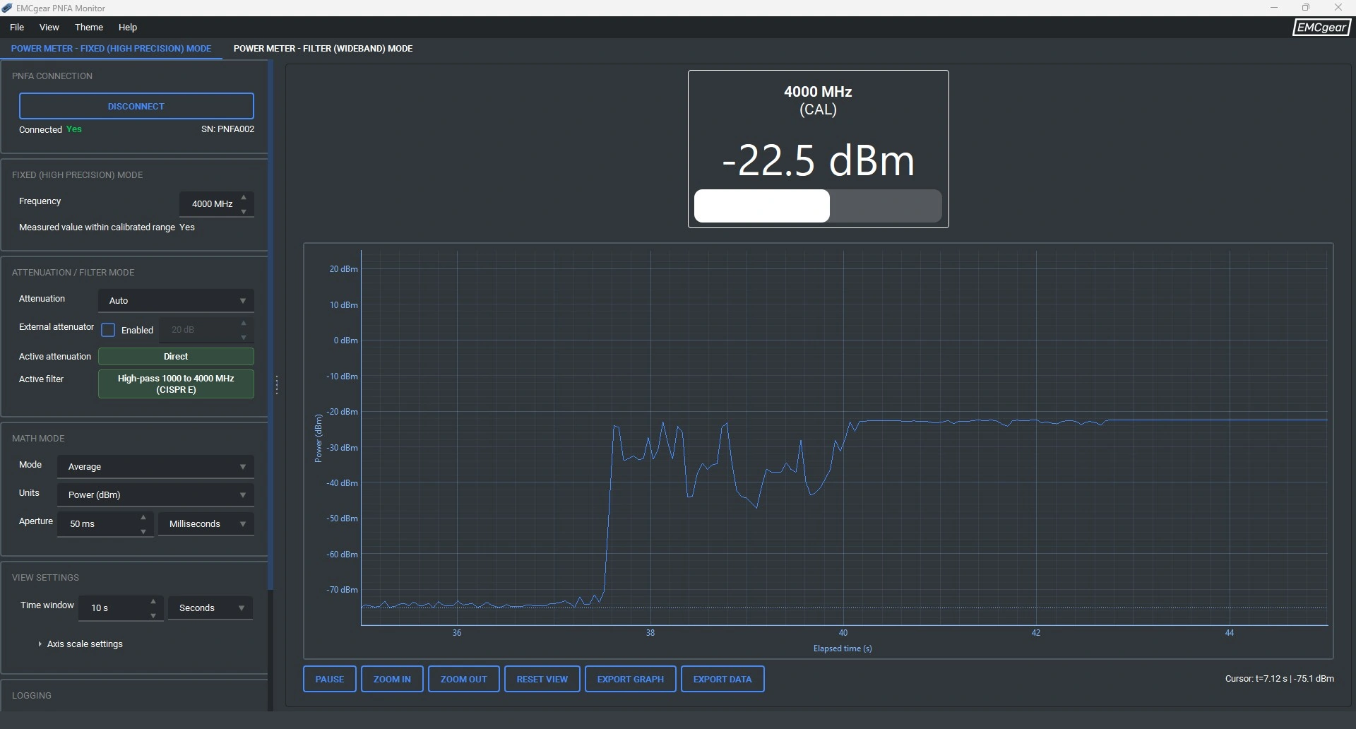
Connect over USB-C to view RF levels, compare time histories and save your measurements. Fixed mode serves known-frequency RF power measurements; Filter mode compares the four broad bands.

PNFA Monitor Fixed high precision interface showing a power readout and RF-level time history

Actual PNFA Monitor interface from the software manual. Displayed readings illustrate the interface.

Up to 1 kSa/s*

* In combination with PNFA Monitor for Windows.

Fast USB recording of RF level

Keep the full received data stream in CSV for later analysis, or save processed graph data for a compact measurement record.

  • Numeric readings, level bars and time graphs
  • Sample, Average, Peak and Max Hold
  • CSV logs, PNG/PDF graphs and saved .pnfa workspaces

Up to 1 kSa/s refers to the maximum RF-level stream rate, not RF waveform sampling or screen refresh. The effective rate depends on measurement mode and setup; it is not a 1 kSa/s-per-band promise in four-band operation. Full data stream logging preserves received frames; graph processing can reduce the number of plotted or exported points.

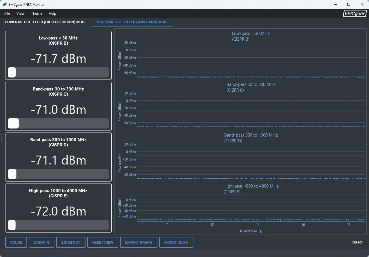
Filter mode

Compare all four bands over time

PNFA Monitor Filter mode with four band readouts and time graphs

Use band visibility, cursors, zoom and adjustable scales to compare emissions before and after a design change.

Graphs show RF level versus time. Keep streaming CSV files separately for the complete recording; a workspace retains the histories still in memory.

Technical specifications

Know the measurement. Know the limits.

Key figures from PNFA Datasheet. Full specifications and operating instructions are available below.

Operating frequency
1 MHz–4 GHz
RF input
SMA female · 50 Ω nominal
Calibrated measurement range
−50 to +20 dBm · 70 dB
Full measurement range
Approx. −75 to +20 dBm · 95 dB
Absolute power accuracy · 1 MHz–3 GHz
Typ. ±0.2 dB · Max. ±0.5 dB
Absolute power accuracy · 3–4 GHz
Typ. ±0.4 dB · Max. ±1.0 dB
Input filtering
LP / BP1 / BP2 / HP + Full band
Feedback
Acoustic + haptic + visual
Display
128 × 64 OLED · Numeric / Graph
Power and PC connection
Battery · USB-C, 5 V / max. 500 mA
Weight and enclosure
70 g · CNC-milled anodized aluminium
Manufacturer warranty
2 years
RF input limits: +25 dBm absolute maximum RF input; this is not the +20 dBm upper measurement limit. Absolute maximum DC input is ±5 V; avoid external DC bias and use an external DC block where required. Software attenuation compensation provides no physical input protection.
PNFA configurations

Choose the kit for your work.

Every PNFA instrument configuration includes the same measurement and feedback capabilities. Choose the accessories for RF power, near-field work, or both.

Included with every PNFA

  • USB-C to USB-A charging/data cable
  • Hard transport case with foam inserts
  • Factory calibration / test report
  • PNFA Monitor for Windows (download)

PNFA

Bring your own probes and RF accessories
€1,090 excl. VAT
PNFA instrument
PNFA
  • PNFA instrument + common package contents
  • For existing RF setups or your own probes
Shop PNFA

PNFA RF power kit

For known-source RF power measurements
€1,149 excl. VAT
PNFA instrument
PNFA
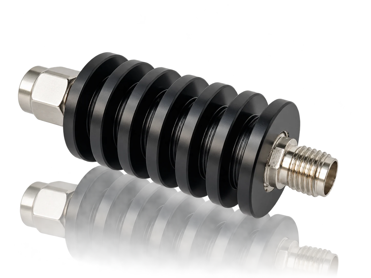
20 dB RF attenuator with finned black body and RF connectors
20 dB attenuator
  • PNFA instrument + common package contents
  • External 20 dB RF attenuator, DC–6 GHz
  • Attenuator: 10 W peak max.; typ. 2 W long term
  • External attenuation compensation in PNFA

Match the physical attenuator to the source power and duty cycle, and keep the PNFA input within its limits.

Shop RF power kit

PNFA Analyzer Kit

For handheld EMI source localization
€1,249 excl. VAT
PNFA instrument
PNFA
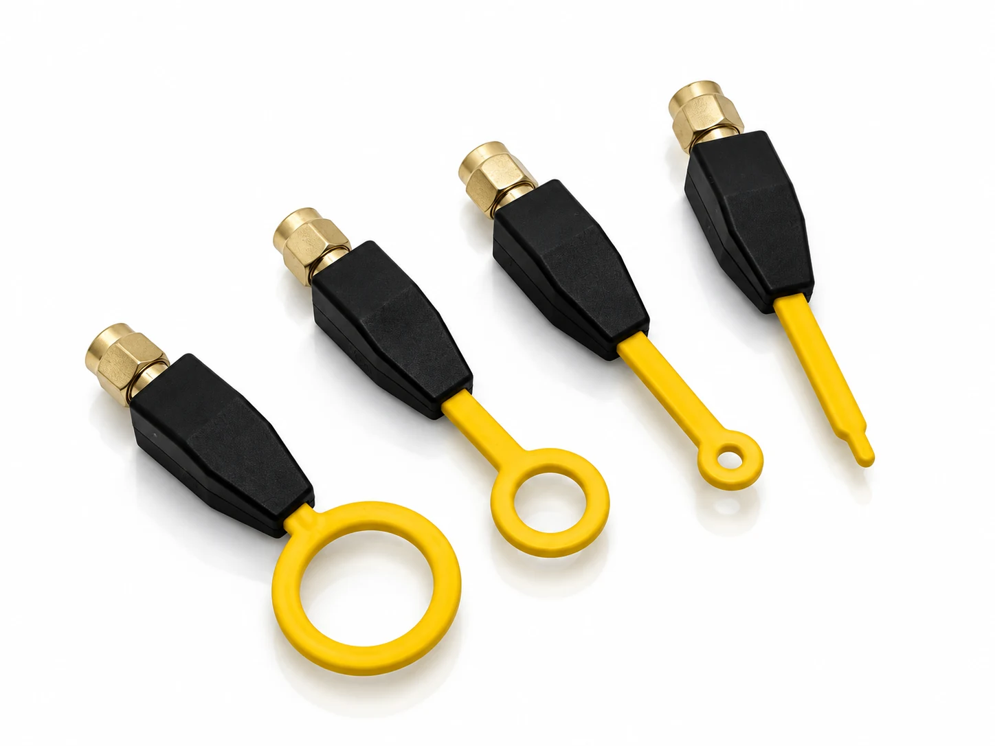
NFPP set of three H-field loop probes and one E-field probe
NFPP probes
  • PNFA instrument + common package contents
  • NFPP set: 3 H-field probes + 1 E-field probe
Shop Analyzer Kit

All prices in EUR, excluding VAT. Based on the PNFA price list dated 10 September 2026.

NFPP probe set: three differently sized H-field loops and one E-field tip
NFPP near-field probes

Choose the probe for the detail.

Three H-field probes with 6, 12 and 21 mm sense-loop diameters, plus one E-field probe with a 4 mm sense tip. Included with the Analyzer Kit and Complete configurations.

Start with the larger H-field loop for a quick area scan, then use smaller loops to pinpoint the source.

Probe readings are power at the PNFA input, not a direct field-strength reading. Keep spacing, orientation, cabling and filter settings consistent for useful comparisons.

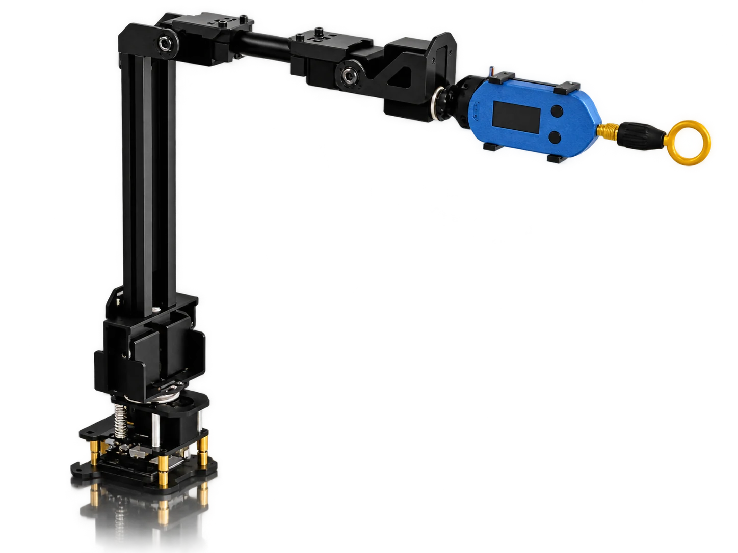
PNFA robotic scanning

Move from handheld search to repeatable positioning.

Available soon

Take the next step in near-field exploration with repeatable probe positioning. Contact us to learn more about upcoming PNFA robotic scanning options and availability.

Illustrative PNFA robotic scanning setup
FAQ

Find the right tool for the measurement.

Can I use PNFA as a standalone RF wattmeter?

Yes. PNFA measures RF power at its 50 Ω SMA input and displays dBm or watts without a PC. For a known-frequency source, select Fixed high precision mode and enter its frequency. Use the appropriate input path and calibrated range; add physical external attenuation when required.

How does it help with handheld near-field troubleshooting?

Attach an E-field or H-field probe and follow the live RF level with sound, vibration and the OLED display. Start in Full band, then select the relevant broad band. No frequency-sweep setup is needed for this level-based search. Connect to PNFA Monitor when you want PC time graphs and recording.

Does “no frequency sweep” mean all bands are measured simultaneously?

No. In a selected filter band, PNFA directly follows RF level without sweeping frequency points. Full band sequentially samples four filter paths and reports the strongest result, not the sum. It does not resolve individual frequencies as a spectrum analyzer does.

Is typical ±0.2 dB the uncertainty of every measurement?

No. It is the datasheet’s typical absolute RF power accuracy figure for 1 MHz–3 GHz. The maximum figure is ±0.5 dB; at 3–4 GHz the figures are ±0.4 dB typical and ±1.0 dB maximum. Use Fixed high precision with the correct known frequency in the calibrated range. Overall setup uncertainty also depends on source conditions, mismatch, cables and attenuators. Near-field probe readings additionally depend on coupling and geometry.

What does “up to 1 kSa/s” refer to?

The maximum USB streaming rate for measured RF level values when recording data with PNFA Monitor for Windows. In Wideband mode, with all four RF filters enabled, a streaming rate of 1 kSa/s represents one complete measurement cycle across all four filter bands. Cyclic switching and measurement of all four filters are completed within this cycle time, and the resulting values for all four bands are reported accordingly.

Can I connect a transmitter directly?

Determine its RF power and DC content first. PNFA measures up to +20 dBm at its input; +25 dBm is the absolute maximum RF input rating, not an operating target. Use suitable physical attenuation and DC blocking where required. The 20 dB attenuator included with the RF power kit and PNFA Complete is rated 10 W peak maximum and typically 2 W long term. Entering attenuation compensation only corrects the reading and does not protect the input.

Does PNFA replace a spectrum analyzer or an EMC compliance receiver?

PNFA is intended for RF power measurement, source localization and comparative EMI troubleshooting. Its four broad filters do not resolve individual spectral components, and its graphs show level over time. Use frequency-resolved instruments when you need a spectrum, and the appropriate test setup for formal compliance measurements.

Which kit should I choose?

Choose PNFA if you already have RF accessories. Choose the RF power kit for the included 20 dB attenuator, the Analyzer Kit for the four NFPP probes, or PNFA Complete for both. All four use the same PNFA instrument and include PNFA Monitor, a USB cable, carrying case and factory calibration / test report.

Measure the power.
Find the source.

PNFA brings both workflows into your hand.

Choose your PNFA